Axel Mulder, School of Kinesiology, Simon Fraser University
This text is published in PCVR 16 pp 10-14. Stoughton, WI, USA: PCVR Magazine, 1994.
© Copyright 1994 Axel Mulder. All rights reserved.
You can get this paper including the software and pictures here.
I have always found it a challenge to make things at virtually no hardware cost, using old parts in innovative combinations. Whilst such projects are usually quite time consuming, they do give you the pleasure of "being independent of the industry" and their picture of the state of the art of technology. Although I wouldn't claim any state of the art for the project described below, I still think it is of value for many an "independent technerd" or even an "independent artist", of which there seem to be a growing number.
But let's get practical. The text below describes how I went about making a real cheap glove interface, that still achieves considerable accuracy while improving the comfortability. Essentially, I purchased a bunch of PowerGloves (PG's), took out the flex sensors, inserted them in sheaths on a lycra glove and suit, hooked them up with a multi-channel serial A/D converter and had a host computer sequentially query the serial interface for the value of each sensor in real-time. These values then were used to control various electronic musical devices.
To obtain the PG sensors, make an incision (it almost feels like surgery) inbetween the middle- and the ringfinger and inbetween the index and the thumb, in the glove's grey soft plastic material. The sensors can be pulled out, sometimes with quite some force (don't worry, they are quite robust, but don't fold them over sharply), because the sensors are secured in a transparent plastic sheath. Then they have to be desoldered.
The PG sensors are sensitive to flex in one direction only. The principle behind the sensors is fairly simple: one side of the substrate of the sensor is coated with a high resistance ink that increases resistance when stretched. Over this ink patches of low resistance ink are deposited, such that only small transversal strips of the high resistance ink contribute to the stretch effect. The stretch is effected by bending the sensor; one side of the sensor will stretch (a little bit) whilst the other side will compress (a little bit). Unfortunately the ink is far more sensitive to stretch than to compression, hence the unidirectionality. This non-linear behaviour extends into ca. the first 15 degrees of the sensitive direction. Beyond that the resistance changes linearly with the angle and ranges from ca. 100 kOhm to 500 kOhm. In order to avoid this non-linearity it is advisable to employ some sort of pre-loading of the sensor, i.e. to have the sensor flexed, although the joint is actually straight. The angular range of a sensor is more than enough for unidirectional angle measurement of almost any human joint. For bidirectional joint movements it is necessary to join two PG sensors back to back. The sensor is by no means calibrated, so that each sensor has its own angle vs. resistance relationship.
It is important to note that the technique of a flex sensor that measures the jointangle by simple mechanical transfer of the joint angle is quite limited. For instance, it is quite difficult to measure the movements of the thumb's carpo-metacarpal joint, with its many degrees of freedom, accurately with a flex sensor, due to skinmotions and the presence of tendons. The metacarpo-phalangeal joints of the index, middle- and ringfinger do not lend themselves very well for this technique either, due to tendons that move under the skin and skinmotions. Ab- and adduction of fingers may be possible by putting a sensor on its side so that it is bent almost 180 degrees - this is the way it is done in the Virtex Cyberglove from Jim Kramer at Stanford.
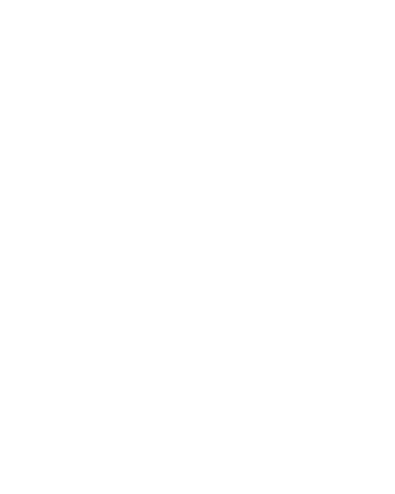
For finger joints it is necessary to have shorter sensor lengths. This can fairly easily be done by cutting the sensor in 2 or 3 parts and attaching new leads. This of course will affect the resistance range of the sensor. Making proper galvanic contact with the sensor's low resistance conductive ink is not a trivial problem however. My first try was to drill tiny holes (less than 1 mm diameter), put a wire through them, fold the wire over and stabilize it with conductive epoxy glue and regular epoxy glue.. This will hold for quite a while, but the hardening of the epoxy will sooner or later screw up the bond, as the sensor substrate keeps on flexing. Lately I have re-examined the problem and used conductive silicone glue, which remains more flexible, to attach a tiny sheet of folded metal (which fits over one end of the sensor) with a tiny hole in it. Drilling a tiny hole through the sensor and putting a wire through the hole and then soldering it on both sides of the sensor stabilizes the connection very well, whilst still keeping things small (click here to see a picture of this). The mini-scale of things requires proper selection of wires too. I have used coaxial cable with teflon isolation of ca. 2 mm diameter, but this may be hard to obtain. It should be equally possible to use twisted pair wires (e.g. wires used in nerve stimulation experiments), as longs as they are kept short. It is recommendable to cover the lead-sensor interface with some heat-shrink tube.
The sensor surface, after attaching leads, should be properly insulated to avoid galvanic contact with the skin, e.g. by spraying some plastic on the surface. It is also possible to use more heat-shrink tube, but this may further increase the stiffness of the sensor, whilst the sensor is already quite stiff. Last but not least it is good practice to shield the sensor, as it is a high impedant device, from the ever present electromagnetic interference by attaching or perhaps spraying a highly conductive layer on both sides of the sensor and (virtually) grounding this layer, i.e. keeping it at zero potential. Whilst some of the above suggestions may not be easy to implement, they may provide a possible solution if a simpler implementation is working insufficiently. I have spent some effort in locating the manufacturers of the sensor, but unsuccesful. A company called Amtec was mentioned many times in Internet Newsgroups as the manufacturer, but they don't seem to exist.
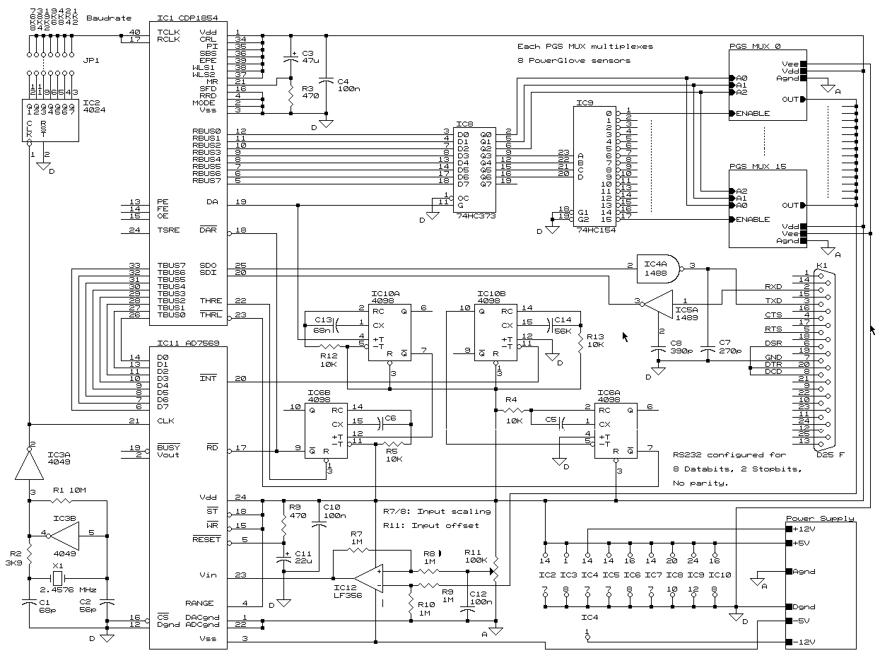
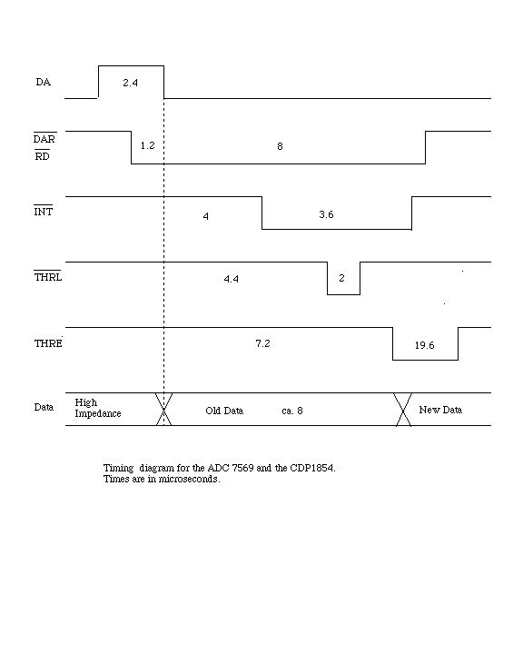
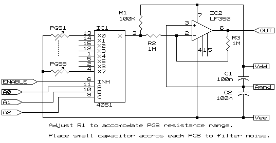
The serial A/D converter was initially based on an design published in Elektuur (Elektor), a dutch electronics magazine. However, besides some serious errors in their design, I also needed a faster A/D chip. Thus I made a new design (click here for a picture of the main schematic) that used the 8 bit AD 7569 with a 2 microsecond conversion cycle (click here for a picture of the timing diagram). This speed would allow me to sample much more channels than I would be using (ever ..). In effect the sampling rate was now not anymore determined by the A/D chip but by the baudrate. Unfortunately, the most common serial interface (RS232) limits the baudrate around 19200 baud (8 databits, no parity, 2 stopbits). It is possible to use higher baudrates, but cable length and proper impedance matching of the serial cable becomes very crucial. Therefore, obtaining the value for one channel takes about 1 ms, so that the sampling rate is ca. 1kHz / #channels. The A/D converter on the mainboard is supplied with channel values via a little board with a multiplexer that connects to the sensors with short wires (click here for a picture of the multiplexer schematic). The 8 PG sensors are connected in series, via the multiplexer, with one resistor, such that the output voltage range of each PG sensor is within the A/D converter input voltage range. This resistor has to be adjusted for different sets of PG sensors. Unfortunately each PG sensor has a different resistance range so that care has to be taken in joining a set of PG sensors, as otherwise the loss of resolution becomes unacceptable.
The resolution is somewhat limited, dependent on the particular joint. The angular range of the joint normally does not use up the available voltage range of the A/D converter (a margin has to be left to allow the joint to flex further than in the calibration phase), whilst each sensor has a different resistance range (see above), so that there is effectively less than 8 bit resolution. For finger joints it is desirable to have ca. 0.5 degree resolution. Whilst the sensor may have a resolution of 0.5 degree, do not confuse this with an accuracy of 0.5 degree. Such accuracy is not easily achieved because of skin movements, unpredictable movements of the sensor, etc.. Of course it is possible to interface other sensors to the A/D converter. In fact, when I first started to work on my ideas for human interfacing, I built a flex sensor by stacking piezo foil layers - super sensitive and very flexible, but also very high impedant (Mulder 1988). As for a PCB of the design: due to the fact that making PCB's is such an incredibly tedious job I have avoided making one upto now. I am "celebrating" the fact that the system is still running on an experimentor's board for more than 6 years now ! (click here for a picture of the power supply schematic)
Somehow I have never been able to become an addict of one particular computer manufacturer. Therefore, I ended up writing code for the IBM PC, the Atari ST and the Apple Mac. This was an especially teeth grinding experience because interrupt programming is a nightmare. Computer manufacturers seem to think that real-time programming is just not an issue, so why bother making their system transparent to programmers in these matters ? Whilst the IBM PC is fairly well documented, I didn't succeed in understanding the Atari ST's interrupt system completely. It is especially the keyboard interrupt that is annoying me. For the Mac I avoided the issue altogether by using the real-time graphical programming environment called MAX, well-known by computer-musicians and musicians who use a computer in their performance. The code that is included with this article should be working, but I decline any responsibility for malfunctioning. I have done my best to make the code work fast, by writing the real-time parts in assembly. Normally, it would be wise to filter the data in software. I have not taken the effort to add code for that. Also, to linearize the sensor it would be easy to write some code that would calibrate values by either simple table look-up or even using formula that approximates the behaviour of the sensor. The code for the IBM PC is written in Borland TurboPascal 5.5 using some of the Blaise Power Tools Plus 5.0 units. Code for the Atari ST is written in Borland C 2.0 and using the included assembler.
The description sofar has covered the raw system, but not an actual implementation of it. I have used it for interfacing finger motions via a lycra glove (e.g. from HIND, type Drylete, which I purchased at Sports City in Boston, MA USA) and arm & leg motions via a lycra suit (e.g. used by speed skaters or dancers). The design of a glove or suit that fits comfortably and ensures a proper transfer of the jointmotions to the sensors is almost an art (for a non-cloths-designer). I have sewn sheaths onto the glove and suit in which the sensor fitted. This works better than e.g. glueing the sensor with siliconeglue onto the lycra, which bond wears out too easily. It is difficult to make the sensor stay in the proper location, especially on the smaller joints; skin movements, movements of the lycra, movements of the sensor in the sheath etc. distort the angle measurement. Stiff leads to the sensor can decrease accuracy. Perhaps an idea for sensor stabilization would be to fill the "holes" between your knuckles with some fabric, so that the sensor always stays on top of the joint. But in fact, what is needed is a sensor that is just as flexible and stretchable as our own skin. Last but not least, make sure the sensor is properly insulated, because sweat gets in everywhere.
My main interest is in making music, particularly controlling timbre, with gestures and other body motions. To that purpose I have hooked up an 8 channel glove with a Roland D10 keyboard synthesizer, only to discover that the D10 hardly allows any real-time patch programming. Much more interesting was an experiment and performance with an 8 channel body suit controlling a Lexicon LXP 5 effectsprocessor that processed the voice of the performer. It is weird to affect your voice so directly with such expressive movements of your extremities. For those interested, I have written some of my ideas about this in (Mulder 1992) and (Mulder 1994). Contact me for a copy.
Currently I am building a system that uses a 68HC11 microcontroller to interface (using the Serial Peripheral Interface) a number of serial 10 bit A/D converters, allowing for fewer cables on the body and more resolution. Then I am trying to find a cheap way to make a wireless connection to the host computer. With respect to applications, whilst continuing to work on musical performance through gestures and dance, I am also looking at interfacing a glove or even a suit to a character animation package called LifeForms, that was entirely developed here at Simon Fraser University. Although the human interfacing problem is not solved at all and keeps on eating up my time, I am most interested in thinking about how the future of musical performance will look like and, more generally, what the essential technical characteristics are of human communicating movements, such as gestures. For those interested in the field, a non-technical overview of current glove interfaces can be found in (Sturman 1994).
Sci.Virtual-Worlds Newsgroup.
Glove-list Listserver (listserv@nas.nasa.gov, a FAQ about the PowerGlove is maintained by the listeditor J.E. Townsend).
(author unknown), (1986). Seriele A/D omzetter. Elektuur, October, pp 74-79.
Eglowstein, H., (1990). Reach out and touch your data, Byte (July) pp 283-290.
Franco, S., (1988). Design with operational amplifiers and analog integrated circuits. New York: McGraw-Hill.
Gardner, D.L., (1989). The powerglove, Design news v45 n23 (December 4) pp 63-68.
Horowitz, P., Hill, W., (1986). The art of electronics. London: Cambridge University Press.
Pallas-Areny, R., Webster, J.G., (1991). Sensors and signal conditioning. New York: Wiley-Interscience.
Mulder, A.G.E., (1988). A piezo-electric flex sensor for a hand gesture interface. Unpublished Masters thesis, Department of Physics, State University Groningen, The Netherlands.
Mulder, A.G.E., (1992). Viewing dance as instrumental to music. Interface (published by ACCAD, Ohio State University, USA) v4 n2 (November) pp 15-17.
Mulder, A.G.E., (1994). Virtual musical instruments: Accessing the sound universe as a performer. .
Sturman, D.J., (1994). A survey of glove-based input. IEEE computer graphics & applications v14 n1 (January) pp 30-39.